Friday, 16 December 2011

Design Proposal


This my proposed design for our final, it doesnt concentrate too much on Barry's designs, but does include a basic transformer for output. Below is our final circuit. Which will most likely have to be modified as we have Yet to have any lab time.
Once again, please organise the labs better!
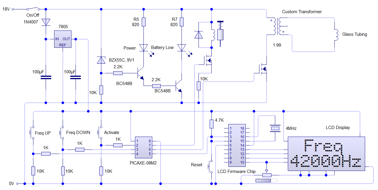

Final Circuit


Due to having limited board space since our product has to be handheld, and with our early casing designs being that of using a drill casing. I have decided to place the circuitry in the main body of the drill, allowing Barry to have the battery compartment for his transformer. I have decided to use the most possible space of the drill body by separating the circuit into 3 sections, or modules. In a similar way to that of my prototyping. Below show how the 3 layers will fit inside the body.


Proposed design of stripboard inside casing

My available workspace for the moment is 40x70mm for the top and bottom layers, and 50x70mm for the middle layer. The length of these boards could be increased to 90mm if the solenoid is placed elsewhere, however for the moment, I have mentally placed the solenoid just in front of the stripboard.

Keeping in line with my work process so far, the sections of stripboard will hold certain modules of the circuit. The bottom layer will contain the voltage regulator along with voltage indicators, this seems sensible because batteries, along with indicators will placed near the bottom of the device. The middle section will most likely hold the PIC along with components for the LCD display, Leaving the top board with the outputs for the gas and transformer, this is suitable as it can be reduced to allow wires for power and LCD to feed up through. With this in mind I will began to make initial Veroboard layouts.

Programmer:

To begin with a simple programming ciruit will have to be contructed for the PICAXE as it requires a 3.5mm  stereo socket to be programmed. The circuit below will be contructed for two reasons, one being that the socket used is not breadboard friendly, so it will assist in prototyping. Also, since the chip will only be programmed once there is no need for it on our final design, so space is saved.

Circuit of Programmer


Veroboard layout of programmer
Parts List:

Part                                          Quantity                Cost (£)        Total Cost(£) 
3.5mm Headphone socket             1                      0.08              0.08
3 pin header                                  1                      0.009            0.009
10K Resistor                                1
22K Resistor                                1

Total cost                                                      0.089


Power Section:

This layer consists of indicators for the the voltage along with a regulator to supply the PIC board with 5 volts. Feeds into this board are the battery and the main On/Off switch, the feeds off it, are the 18V, 5V and 0V rails.


Circuit for Power layer


Veroboard layout (in black) of Power layer


Parts List:

Part                                          Quantity                Cost (£)        Total Cost(£) 
SPST Switch                                 1                     0.50              0.50
1N4001 Diode                               1                     0.024            0.024
7805 Voltage Regulator                  1                     0.17              0.17
Zener Diode                                   1                     0.011            0.011
Green LED                                     1                     0.036            0.036
Red LED                                        1                     0.036            0.036
BC108 Transistor                            2                     0.193            0.386
PP3 Battery Snap                          2                     0.46              0.92
100µF Capacitor                            2
10K Resistor                                  1
2.2K Resistor                                 2
820 Resistor                                   2

Total cost                                                                                   2.083


PIC Section:

For the middle layer, the PIC along with the LCD driver chip and the 3 main inputs to the device have been.
With this initial design, the board has reached its designed limit of 19x28 holes, which I have calculated form the dimensions in millimetres. 


Circuit of middle layer


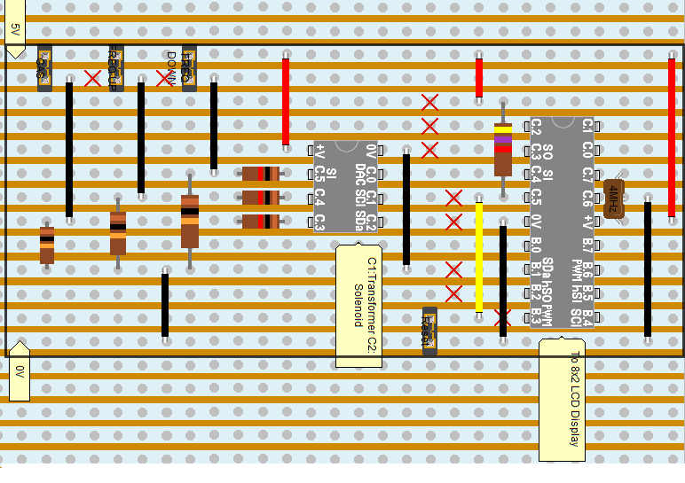
Veroboard layout of main section


Parts List:

Part                                          Quantity                Cost (£)        Total Cost(£) 
PIC16F629                                    1                     0.64              0.64
PIC16F819                                    1                     1.512            1.512
4MHz Resonator                            1                     0.08              0.08 
PTM switch                                    3                     0.247            0.741
8 Pin IC Socket                              1                     0.02              0.02
18 Pin IC Socket                            1                     0.03              0.03
9 Way Ribbon Cable                      1                     1.02              1.02 
10K Resistor                                  3
1K Resistor                                    3
4.7K resistor                                  1

Total cost                                                                                   4.052


Outputs Section:


This will be a the top and final layer of the overall circuitry. It will be a very simple board, but will help in its reduced size to allow wiring for the LCD module and other inputs to feed through. Also, if anything burns out, only one small board will be changed instead of the entire thing, which will keep cost and time to a minimum. The 18v rail will feed from the initial power board, and outputs for the solenoid, (which will control the gas) and the frequency for the transformer will be the outputs


Circuit for Output Board


Veroboard layout of Outputs


Part                                          Quantity                Cost (£)        Total Cost(£) 
1N4001 Diode                               1                     0.024             0.024
Mosfet                                            2                      0.38              0.76 
10K Resistor                                  2

Total cost                                                                                   0.784


Complete Parts List


Part                                          Quantity                Cost (£)        Total Cost(£) 
Programmer                                   1                      0.089           0.089
Power Section                                1                      2.083          2.083
PIC Section                                    1                      4.052          4.052
Outputs Section                              1                       0.784          0.784
LCD 8x2 Display                             1                       2.22             2.22
Solenoid                                         1                       0.987          0.987
                                                                                               

Total cost for circuit of project                                                £10.215


As you see, this is our design proposal. Although prices for resistors and capacitors have been omitted from the final price, in addition to cost of wire and veroboard. We feel, even with those prices added we would still be under our initial £15 budget. With this, we have given ourselves a five pound allowance, in case any extra, or replacement components need to be ordered.


Tuesday, 13 December 2011

Development of final idea


Input:

For the input that will feed into the PIC will be simple push to make (PTM) switches. Below shows 3 PTM, one for the activation of the gas and two for varying the frequcy. Each switch has a 10K pull down resistor to stop any fluctuations as well as a 1K feeding into the PIC to smooth the signal going in. This design also reduces valuable board space.

Inputs to PIC chip


Control:

The control of the circuit will be the PICAXE-08M2 microcontroller. The reason for choosen this is that it allows for the same board space, if not less, than a 555 timer. Also it has the same memory capacity as its 14 pin older brother. Although there could be complications with regards to programming the LCD. Also there is 256 btyes of Electrically Erasable Programmable Read-Only Memory, (EEPROM) which should be more than enough to store the value of the frequency. There are also 6 configuarablable input/output pins, which should be enough for our needs. Below shows the -08M2 with programmer.


8 pin PICAXE


The design for this programmer circuit was found from the PICAXE start up guide, which can be found here


Output:

For the outputs of the circuit I have decided to use a solenoid in a normally closed state to control the gas, this will allow the gas to stop flowing if power is cut. For the output to the transformer, a simple darlington pair transistor or power Mosfet will be used from the frequency pin of the PIC. A 12 or 18v will be placed on the collector/source as this greater voltage will allow for less turns on the transformer. For the solenoid a schematic is shown below


Solenoid with input from PIC


 A 10K pull down is used to pull any signal low from the PIC, while this feeds into a Mosfet. A protective diode is placed across the solenoid to stop any voltage coming back.


Additional Circuitry:


5 Volt regulator: 


In addition to the PIC circuit a 5 volt regulator would also need to be constructed as this PIC requires 5 volts to operate. Below shows the circuit for a 7805 voltage regulator, this will provide the PIC with a 5V, 1A continuous supply. Also shown are the smoothing capacitors and protective diode.


7805 Voltage regulator


Voltage Indicator:

In addition to the regulator, I have decided to add an indication circuit, which consists of an indicator LED which tells the user that the device has power running to it, as well as an indicator LED to say when the battery is low. This happens when the voltage falls below 9.1 volts


LCD display with driver:

One of the options to display the frequency is with an LCD display. For our project I have decided to use an 8x2 blue backlit display. The advantages being that it is a much cheaper option than the LCD counter module, with displays selling for around £2-3 and also will provide a more accurate reading than that of the LED indicator. Also, only one pin from the PIC is being used. However it does take up a lot of precious board space, as well as physical space of an eventual casing. Also since the 8x2 has been superseded by the 16x2 or even its 20x4 counterparts, getting the display to prototype will be exceedingly difficult . Which is why we have came up with two options in case this plan does not work. Belows shows the lcd with its own driver circuit. An optional backlit button has been added. However the device may be constantly in the final prototype


LCD display with driver


LCD counter module:

Another approach would be to use a miniature LCD counter module like this one. It would be incremented from the PIC in thousands. A decal on the device could be used to display the term 'Hz' to show the user that frequency is the value being displayed. This design, although easier than the LCD and uses just as much board space as the LED design. It does require the user to manually reset the LCD as by this point all the PIC I/O pins will be in use. The only alternative to this is to remove the Frequency Down or Frequency Up input.

LCD Module Counter


LED frequency indicator


In case the two aforementioned ideas do not work, a much simpler indicator LED will be used. The PIC will use Pulse Width Modulation to change the brightness of the LED to tell the user that that frequency is either Low, Medium or High. The circuit for this requires a high brightness LED and a protective resistor from the PIC pin.

LED Frequency Indicator


Evaluation of three ideas


Idea 1:

  • Doesn't allow a variable frequency 
  • Rather simplistic design for a second year project
  • Use of solenoid adds an important safety feature
  • Gas canisters are much too large for a portable device
  • Does not employ a way to display the frequency  

Idea 2:
  • Servo would still allow gas to flow if power was cut
  • Does allow for a varied frequency
  • Duty can also be altered unlike 555
  • Allows for a way for frequency to be displayed
  • Although cheap, it is the most expensive option
  • Takes up a rather large and limited PCB space in a handheld device

 Idea 3:

  • Variable frequency can be achieved
  • No precise measurement or display of selected frequency 
  • Frequency can be easily calculated
  • Components are inexpensive
  • The gas canisters/chargers are rather expensive, however are perfect for a portable application

Development of chosen idea:

For our final idea, we have decided to use push to make switches as our input to alter the frequency. Also, it will be the input to control gas flow. For the control we are going to use an 8 pin PIC. This will allow us to cut down on board space as it has the same layout as a 555 IC, also the 8 pin is a much cheaper option than its larger counterparts. This will keep our costs down an in-line with the 555 and Mosfet options. For the output we are going to source a normally closed gas solenoid, as this has an included safety feature, in addition to being easily controlled via PIC, unlike its servo alternative. For the display of frequency, we are going for 2 options, our first being an LCD display, which will change according to the user input of frequency. Since this adds a great deal of complexity to our design in terms of PCB size allocation and programming. We have decided on a back up of a more simpler LED which will vary in brightness if the frequency is either Low, Medium or High. Since this is a portable application, designs for a voltage regulator for the PIC chip, along with indicators for battery level will also have to be designed and added.

Idea 3


For our final idea, we have decided to use a 555 timer to produce our frequency with a variable resistor to alter the frequency. The gas will be controlled by a simple regulator.

Input:

 The input to our circuit will either be a variable resistor for varying the frequency of the 555 timer. Another option would be to use a rotary switch switch as a single pole 5 throw with a predetermined resistor. The advantage of this would mean that a set frequency could be achieved. Decals or labels could be used on the device to tell the user the frequency.


Rotary Switch


Control:

For the control, we have used a 555 timer in astable configuration to provide our frequency.
The frequency, of the output pulses is determined by the values of two resistors, R1 and R2 and by the timing capacitor, C.
The design formula for the frequency of the pulses is:


The period, t, of the pulses is given by:


The HIGH and LOW times of each pulse can be calculated from:


The duty cycle of the waveform, usually expressed as a percentage, is given by:


Fro, this we calculated the values of our resistor and capacitor so that the frquency can vary between 2 and 8KHz. Below shows a simple schematic of our circuit

555 in Astable mode


Output:

The gas output of this idea takes a more mechanical approach. The gas will be controlled by a built in regulator such as this one below


Mini CO2 regulator


This regulator will be used in conjuction with a helium canister or 'charger' like this. The problem with this concept is that the chargers fro helium are rather expensive, however it is the easiest route to go.


Idea 2

Control:


For our second idea I decided on a simple microcontroller to output a high frequency. After much research and keeping the cost in line with my other ideas, I settled on the PICAXE series of microcontrollers, which are based on the range of Microchip PICs. Not only are these chips available in DIL packages, (A stipulation for our project) but also have inexpensive start up costs. The programmer being a simple Serial to 3.5mm connector
Below shows a 14 pin Pic called the PICAXE 14m. The advantage with this over the the Mosfets is that the frequency can be varied.


Output: 


Idea 1

Control:

For our first idea we decided to use a voltage source inverter using Mosfets to give our frequency


Voltage source inverter

I began modelling a simplified circuit on Livewire which is based on that from
http://escholarship.lib.okayama-u.ac.jp/electrical engineering/2

The idea for this was to feed into a third order resonance circuit then onto a step up transformer

A simple on/off switch would be used to power this part of the circuit.

Output:


For the control of the gas I decided to use a small canister of helium. These were found to be relatively cheap. Another option would be to use Nitrogen, another inert gas, however industry does not seem to produce them in such small canisters at the helium


The helium would be controlled by a solenoid, which acts in a normally closed state. This adds a safety aspect to the project, in the case that if power was cut from the device, the gas would cease to escape.
The solenoid would be controlled via a simple push to make switch from a separate 12 volt supply


N/C Solenoid with PTM switch


Saturday, 10 December 2011

Ideas for Electronics

Since the labs in the University of Liverpool are So lovingly organised in such a way. That parts for a project that takes place in February for four weeks, Has to have a parts sheet listing all the components you are going to use, and Somehow expect you to have a near enough completed circuit diagram to pull outta your head in Mid-December.....
I do apologise if no research is at the section, as I unfortunately have to rush into circuit ideas to make a completed parts list for Monday. Absolutely ridiculous!

Please organise the lab projects better, this goes for Year 1 as well!!

Anywho, from Dr Taylor and the brief research Barry and I collated, we found that a circuit that generated a pulse at 2-8KHz that fed into a hand built transformer to generate around 2KV that would excite an inert gas like helium into a plasma. Dr Taylor also added that a display of the frequency would be a nice addition to the circuit. From this Barry and Me drew up a simple specification.

Spec:

  • Device has to be portable, so battery powered
  • High frequency pulse generator circuit
  • Variable frequency (if possible)
  • Way to display frequency (if possible)
  • Ideal way to control the flow of gas 
  • Addition of safety features 

From this I would use my research in addition to my own material to draw up three ideas. I have deceided the best way to go about this is by a modular approach. By splitting up the input, control and output, this allows not only my circuit designs to be easier, but also fault finding when it comes to prototyping. In addition if one part fails on inspection day, at least we can demonstrate that other parts of the circuit function well.

Brief introduction

For our second year project myself, Michael John Lynch and my wonderfully brilliant lab partner, Barry Smith have chosen to design and build a micro plasma generator

After a short brief with our tutor, Dr Taylor (Thursday 24th November 2011) and some initial research. We found three core elements to the project, the electrical, electronic and mechanical side. We decided that Barry should take the electrical side, and I the electronic side, and we would work together on the mechanical aspect.