Input:
For the input that will feed into the PIC will be simple push to make (PTM) switches. Below shows 3 PTM, one for the activation of the gas and two for varying the frequcy. Each switch has a 10K pull down resistor to stop any fluctuations as well as a 1K feeding into the PIC to smooth the signal going in. This design also reduces valuable board space.
 |
| Inputs to PIC chip |
Control:
The control of the circuit will be the PICAXE-08M2 microcontroller. The reason for choosen this is that it allows for the same board space, if not less, than a 555 timer. Also it has the same memory capacity as its 14 pin older brother. Although there could be complications with regards to programming the LCD. Also there is 256 btyes of Electrically Erasable Programmable Read-Only Memory, (EEPROM) which should be more than enough to store the value of the frequency. There are also 6 configuarablable input/output pins, which should be enough for our needs. Below shows the -08M2 with programmer.
 |
| 8 pin PICAXE |
The design for this programmer circuit was found from the PICAXE start up guide, which can be found here
Output:
For the outputs of the circuit I have decided to use a solenoid in a normally closed state to control the gas, this will allow the gas to stop flowing if power is cut. For the output to the transformer, a simple darlington pair transistor or power Mosfet will be used from the frequency pin of the PIC. A 12 or 18v will be placed on the collector/source as this greater voltage will allow for less turns on the transformer. For the solenoid a schematic is shown below
 |
| Solenoid with input from PIC |
A 10K pull down is used to pull any signal low from the PIC, while this feeds into a Mosfet. A protective diode is placed across the solenoid to stop any voltage coming back.
Additional Circuitry:
5 Volt regulator:
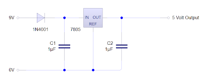
In addition to the PIC circuit a 5 volt regulator would also need to be constructed as this PIC requires 5 volts to operate. Below shows the circuit for a 7805 voltage regulator, this will provide the PIC with a 5V, 1A continuous supply. Also shown are the smoothing capacitors and protective diode.
 |
| 7805 Voltage regulator |
Voltage Indicator:
In addition to the regulator, I have decided to add an indication circuit, which consists of an indicator LED which tells the user that the device has power running to it, as well as an indicator LED to say when the battery is low. This happens when the voltage falls below 9.1 volts
LCD display with driver:
One of the options to display the frequency is with an LCD display. For our project I have decided to use an 8x2 blue backlit display. The advantages being that it is a much cheaper option than the LCD counter module, with displays selling for around £2-3 and also will provide a more accurate reading than that of the LED indicator. Also, only one pin from the PIC is being used. However it does take up a lot of precious board space, as well as physical space of an eventual casing. Also since the 8x2 has been superseded by the 16x2 or even its 20x4 counterparts, getting the display to prototype will be exceedingly difficult . Which is why we have came up with two options in case this plan does not work. Belows shows the lcd with its own driver circuit. An optional backlit button has been added. However the device may be constantly in the final prototype
 |
| LCD display with driver |
LCD counter module:
Another approach would be to use a miniature LCD counter module like this one. It would be incremented from the PIC in thousands. A decal on the device could be used to display the term 'Hz' to show the user that frequency is the value being displayed. This design, although easier than the LCD and uses just as much board space as the LED design. It does require the user to manually reset the LCD as by this point all the PIC I/O pins will be in use. The only alternative to this is to remove the Frequency Down or Frequency Up input.
LED frequency indicator
In case the two aforementioned ideas do not work, a much simpler indicator LED will be used. The PIC will use Pulse Width Modulation to change the brightness of the LED to tell the user that that frequency is either Low, Medium or High. The circuit for this requires a high brightness LED and a protective resistor from the PIC pin.
Another approach would be to use a miniature LCD counter module like this one. It would be incremented from the PIC in thousands. A decal on the device could be used to display the term 'Hz' to show the user that frequency is the value being displayed. This design, although easier than the LCD and uses just as much board space as the LED design. It does require the user to manually reset the LCD as by this point all the PIC I/O pins will be in use. The only alternative to this is to remove the Frequency Down or Frequency Up input.
 |
| LCD Module Counter |
LED frequency indicator
In case the two aforementioned ideas do not work, a much simpler indicator LED will be used. The PIC will use Pulse Width Modulation to change the brightness of the LED to tell the user that that frequency is either Low, Medium or High. The circuit for this requires a high brightness LED and a protective resistor from the PIC pin.
 |
| LED Frequency Indicator |

No comments:
Post a Comment