Programmer:
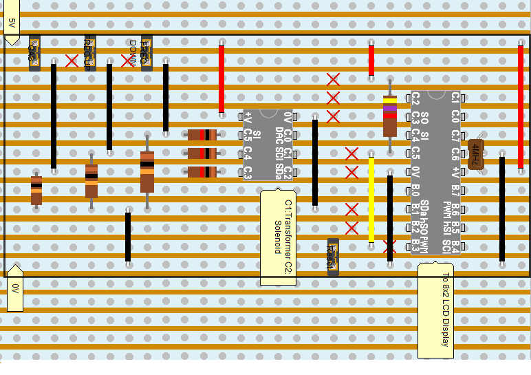
For the development of the PIC I decided to build the programmer first, as this would be a good starting block, with regards practising soldering and veroboard design. From the diagram below I used this as an inital schematic. I began to solder up my programmer.
 |
| Veroboard layout of programmer |
 |
| Prototype of programmer |
PIC Development Board:
I decided to build up a small development for Barry to use for testing with his toroid. I began by modelling up the 5 volt regulator on breadboard from my schematic
 |
| 5 Volt Regulator on Livewire |
As you can see the voltage regulator produces a steady 5 volt supply. Ideal for the PIC chips I will be using.
 |
| Testing of 5 volt regulator on breadboard |
From this I began to model up the PIC chip, and began to test the chip with simple code to blink an LED. The photos below show these various stages.
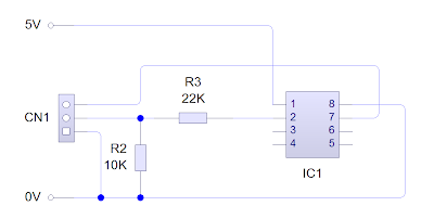 |
| Simple schematic of PIC |
'C:\Users\Michael John\Documents\project\PIC\picdevelopmentboard1.plf
symbol varA = b0
symbol varB = b1
symbol varC = b2
symbol varD = b3
symbol varE = b4
symbol varF = b5
symbol varG = b6
symbol varH = b7
symbol varI = b14
symbol varJ = b15
symbol varK = b16
symbol varL = b17
symbol varM = b18
symbol varN = b19
symbol varO = b20
symbol varP = b21
symbol varQ = b22
symbol varR = b23
symbol varS = b24
symbol varT = b25
symbol timer = time
let dirsC = 010101
label_10:
high 4
pause 5000 'Wait command
low 4
pause 1000 'Wait command
goto label_10
Code to blink an LED every second
 |
| PIC running simple test code |
From this, I decided to build up a small development board to board. The point of this was that Barry had something to use to test with his toroid. Below shows the final develpment board. This board includes a 5 volt regulator for the PIC, an indicator LED, (to show the PIC is functioning normally) a programmer input and 3 outputs. One of these outputs is used for the frequency. Barry will take this output and interface it with his part of the circuit.
 |
| PIC Develpment Board |
I encountered a few problems with this board. Although this has aided me in my final design. After the PIC had been programmed, the internal timing function did not operate correctly. After some fault finding, I came to the conclusion that the SerIn pin was not held low. After added a 10K pull down resistor, I found the PIC could not receive any commands. To counter this I removed the original 10K and added a 3 pin header with a 10K attached. This will be removed when it has to be programmed.
The development board has a simple code written to it, that produces a 4000Hz output, along a a blinking indicator LED.
'C:\Users\Michael John\Documents\project\PIC\picdevelopmentboard1.plf
symbol varA = b0
symbol varB = b1
symbol varC = b2
symbol varD = b3
symbol varE = b4
symbol varF = b5
symbol varG = b6
symbol varH = b7
symbol varI = b14
symbol varJ = b15
symbol varK = b16
symbol varL = b17
symbol varM = b18
symbol varN = b19
symbol varO = b20
symbol varP = b21
symbol varQ = b22
symbol varR = b23
symbol varS = b24
symbol varT = b25
symbol timer = time
let dirsC = 010101
main:
pwmout 2 , 249 ,
500
label_10:
high 4
pause 5000 'Wait command
low 4
pause 1000 'Wait command
goto label_10
Code for the Development Board, producing a 4000Hz pulse
LCD and Firmware:
Since my back up plans for the frequency out are LED based, which are relatively easy to prototype up. Therefore the LCD approach will take much more time to wire up. Unfortunately due to the fact of keeping costs down, the LCD I bought only has 12 pins. Since the datasheet for the LCD was in chinese, and I don't have any chinese friends, I would have to work out the pin out on my own. Most character LCD's have either 14 or a 16 pin configuation. The two extra being for backlit displays. Below shows a standard pin out for a Hitachi HD44780 LCD controller:
- Ground
- VCC (+3.3 to +5V)
- Contrast adjustment (VO)
- Register Select (RS)
- Read/Write (R/W)
- Clock (Enable).
- Bit 0
- Bit 1
- Bit 2
- Bit 3
- Bit 4
- Bit 5
- Bit 6
- Bit 7
- Backlight Anode (+)
- Backlight Cathode (-)
Using the diode function on the multimeter, I found that pins 11 and 12 were for the backlit part of the display. Working off other data sheets I wired the remaining pins up to a PIC16F684. This a a 14 pin chip produced by microchip,it has 11 configurable input/output pins and up to 1800 lines of memory, which should be more than enough to operate as an appropriate LCD driver. My initial circuit design for the LCD is shown below.
 |
| LCD to PIC16F684 schematic |
The PIC, as well as the LCD operates at 5 volts, which is ideal, as I already have a 5 volt regulator included in the circuit. The programmer for the PIC will be the same as the PICAXE-08M2. This will cut down on the amount of overall components needed on the veroboard. The 330 ohm resistor is included to protect the backlit display. The 10K potentiometer is to vary the contrast of the LCD. I used ribbon cable to solder the LCD up, and tinned the other end so the ribbon cable could be easily breadboarded. (Ribbon cable is multicore, rather than single core, which means it is difficult to breadboard with.) Below shows the LCD made up on breadboard with the PIC
 |
| PIC16F864 with LCD connected via ribbon cable |
Using code I found online
here. I plan to modify the code, shown below
        SYMBOL  RS        = 0         ; 0 = Command   1 = Data
        SYMBOL  E         = 1         ; 0 = Idle      1 = Active
        SYMBOL  DB4       = 2         ; LCD Data Line 4
        SYMBOL  DB5       = 3         ; LCD Data Line 5
        SYMBOL  DB6       = 4         ; LCD Data Line 6
        SYMBOL  DB7       = 5         ; LCD Data Line 7

        SYMBOL  RSCMDmask = 000000 ; Select Command register
        SYMBOL  RSDATmask = 000001 ; Select Data register

        SYMBOL  get       = b11
        SYMBOL  char      = b12
        SYMBOL  rsbit     = b13
    PowerOnReset:

        GOSUB InitialiseLcd

    DisplayTopLine:

        EEPROM 6,("Hello")

        FOR get = 6 TO 10
          READ get,char
          GOSUB SendDataByte
        NEXT

    MoveCursorToStartOfSecondLine:

        char = $C0
        GOSUB SendCmdByte

    DisplayBottomLine:

        EEPROM 11,("World!")

        FOR get = 11 TO 16
          READ get,char
          GOSUB SendDataByte
        NEXT

        END

    InitialiseLcd:

        FOR get = 0 TO 5
          READ get,char
          GOSUB SendInitCmdByte
        NEXT

        ' Nibble commands - To initialise 4-bit mode

        EEPROM 0,( $33 )    ; 11---- 11----   8-bit / 8-bit
        EEPROM 1,( $32 )    ; 11---- 10----   8-bit / 4-bit

        ' Byte commands - To configure the LCD

        EEPROM 2,( $28 )    ; 101000 1LNF00   Display Format
        EEPROM 3,( $0C )    ; 001100 001DCB   Display On
        EEPROM 4,( $06 )    ; 000110 0001IS   Cursor Move

                            ; L : 0 = 4-bit Mode    1 = 8-bit Mode
                            ; N : 0 = 1 Line        1 = 2 Lines
                            ; F : 0 = 5x7 Pixels    1 = N/A
                            ; D : 0 = Display Off   1 = Display On
                            ; C : 0 = Cursor Off    1 = Cursor On
                            ; B : 0 = Cursor Steady 1 = Cursor Flash
                            ; I : 0 = Dec Cursor    1 = Inc Cursor
                            ; S : 0 = Cursor Move   1 = Display Shift

        EEPROM 5,( $01 )    ; Clear Screen

        RETURN

    SendInitCmdByte:

        PAUSE 15                        ; Delay 15mS

    SendCmdByte:

        rsbit = RSCMDmask               ; Send to Command register

    SendDataByte:

        pins = char & $F0 / 4 | rsbit   ; Put MSB out first
        PULSOUT E,1                     ; Give a 10uS pulse on E
        pins = char & $0F * 4 | rsbit   ; Put LSB out second
        PULSOUT E,1                     ; Give a 10uS pulse on E

        rsbit = RSDATmask               ; Send to Data register next

        RETURN
Original code found online for a 16x2 LCD
The code above will be modified to accept SerIn commands on pin 3 of the PIC. These commands will feed in from the PICAXE-08M2. The code above is used for a display with a 16x2 format, meaning it is 16 characters across and and 2 lines down. Since the LCD is wired up in a 4 bit operation, I will keep the code in 16x2 format. However I will alter the SerIn commands to send out 16x1 commands, but the LCD will take the latter 8 characters, and place them on a new line. I believe this is achievable in the time I have for this project. Below shows the altered program for the PIC16F864.
'C:\Users\Michael John\Documents\project\PIC\LCDdriver.bas
' *** LCDdriver.bas *** Michael John Lynch ***
' *** Constants *********

 symbol baud   = input0                  ' used to set Baud (hi=4800/lo=2400)
 symbol hi     = 1     ' used to set Baud (hi=4800/lo=2400)
 symbol cmd    = 0     ' used to set up for cmd/txt byte
 symbol txt    = 1     ' used to set up for cmd/txt byte
 symbol enable = 1     ' LCD enable pin = PICAXE output1
 symbol RSin   = outpin0   ' LCD RegSel pin = PICAXE output0
' *** Variables *********

 symbol char  = b10    ' character to be sent to LCD
 symbol index = b11    ' used as counter in For-Next loops
 symbol RSbit = b12    ' used to set  for cmd/txt byte
 symbol temp  = b13    ' used to manipulate char

' *** Directives ***
 '#com4      ' AXE027 USB to Serial cable
 #picaxe14M     ' set compiler mode,


' *** Begin Main Program ***

setfreq m8
gosub Init

do
 if baud = hi then
  serin 4,N4800_8,b0,b1,b2,b3,b4,b5,b6,b7,b8
 else
  serin 4,N2400_8,b0,b1,b2,b3,b4,b5,b6,b7,b8
 endif

 char = b0
 gosub OutByte

 char = b1
 gosub OutByte

 char = b2
 gosub OutByte

 char = b3
 gosub OutByte

 char = b4
 gosub OutByte

 char = b5
 gosub OutByte

 char = b6
 gosub OutByte

 char = b7
 gosub OutByte

 char = b8
 gosub OutByte
loop


' *** End Main Program - Subroutines Follow ***

' *** Init Subroutine ***
Init:
 pins =  0   ' clear all output lines
 pause 200   ' pause 200 mS for LCD initialization

 pins = 12       ' (48/4=12) set to 4-bit operation
  pulsout enable,1  ' send data
 pause 10     ' pause for 10 mS

 pulsout enable,   ' send again
 pulsout enable,1  ' send again (this is needed in 4-bit mode)

 pins =  8       ' (32/4=8) set to 4-bit operation
 pulsout enable,1  ' send data.
 pulsout enable,1  ' send again (again, this is needed in 4-bit mode)

 pins = 32       ' (128/4=32) set to 2 line operation

 pulsout enable,1    ' send data

 char = 12     ' turn off cursor
 gosub OutByte    ' send instruction to LCD

 return


' *** OutByte Subroutine ***

OutByte:
 if char<32 OR char>127 then
   RSbit = cmd    ' set up for command byte
 else
   RSbit = txt    ' set up for text byte
 endif

 temp = char / 4     ' because we're using DB5...DB2
 temp = temp & 111100   ' mask for  DB5 - DB2
 pins = temp   ' place high nibble of char onto pins
 RSin = RSbit   ' RSin = 0 for command, or 1 for text
 pulsout enable,1     ' send data

 temp = char * 4    ' because we're using DB5 - DB2
 temp = temp & 111100   ' mask for  DB5 - DB2
 pins = temp    ' place low  of char onto pins
 RSin = RSbit    ' RSin = 0 for command, or 1 for text
 pulsout enable,1     ' send data

 return
Modified code to run on the PICAXE-14M
The program above will run on a PICAXE-14M, the main reason for choosing this PIC over the original 14 pin I had, was the bootloader on this PIC allows for the use of the programmer I had built. Also the price was similar for both types, so it keeps within our proposed 15 quid budget. The program receives serial data from the main PIC and displays it on the LCD. Since I am using the DB5-DB2 pins since the LCD only supports 4 bit operation. Certain bits need to be divided by 4, or multiplied by 4 to be placed on the correct pins. Even though the program above appears rather crude, and like I said, of how the serial data is configured for a 8x2 display from 16x1 commands. Although the plus side is that it is rather faster, which is needed for the amount of times the display will have to update. By dedicating 9 variables to the reception of serial data, it avoids necessity of the master PIC to delay between the transmission of each character. Another advantage of doing the design this way, is that any firmware chips are roughly 4 to 5 more expensive than blank PICs, and this would not be viable with the budget I have.
'C:\Users\Michael John\Documents\project\PIC\LCDdriver.bas
' *** LCD16x2-CustCharDriver14M2.bas *** Michael John Lynch ***


' *** Constants ***
  symbol  cmnd =      0       ' RSbit = 0 (low) for command bytes
  symbol  text =      1       ' RSbit = 1 (high) for text bytes
  symbol enPin =    B.1       ' LCD enable pin 12
  symbol rxPin =    C.4       ' serial data received on 3

' *** Variables ***
  symbol  char =     b0       ' character to be sent to LCD
  symbol index =     b1       ' used in for loop
  symbol nibHi =     b2       ' the high bit of char
  symbol nibLo =     b3       ' the low bit of char
  symbol RSbit =     b4       ' used to set up for text byte
  symbol  temp =     b5
  symbol RSpin = pinB.0       ' using RSpin as a variable so the form pin 13 is
                                required
' *** Directives ***
  #com 7                      ' set COM port for downloading
  #picaxe 14M2                ' set compiler mode
  #terminal off


' Display on LCD
  data 64,("yo ho ho")
  data 80,("toodles")

' *** Begin Main Program ***

  setfreq m32                 ' run as fast as possible

  dirsB = %11111111           ' all PortB pins are outputs to the LCD
  dirsC = %11000111           ' 4, 3, and 2 are fixed as inputs.

' *** Initialize the LCD ***
  outpinsB = 0                ' clear all output lines
  pause 1600                  ' pause 200 mS for LCD to complete clear

  outpinsB = 12               ' (48/4=12) set to 4-bit operation
  pulsout enPin,8             ' send data
  pause 80                    ' pause 10 mS
  pulsout enPin,8             ' send again
  pulsout enPin,8             ' send again (necessary for 4-bit operation)

  outpinsB = 8              ' (32/4=8) set to 4-bit operation
  pulsout enPin,8             ' send data
  pulsout enPin,8             ' send again (necessary for 4-bit operation)

  outpinsB = 32               ' (128/4=32) set to 2 line operation
  pulsout enPin,8             ' send data

  char  = 12                  ' display on, cursor off
  gosub OutToLCD              ' send instruction to LCD


' *** Indicate "Ready to receive data." ***

  char = 1                    ' instruction: clear display
  gosub OutToLCD              ' send instruction to LCD
  pause 16                    ' minimum 2mS delay for clear display

  char = 128                  ' instruction: go to start of 1st row
  gosub OutToLCD              ' send instruction to LCD

  for index = 64 to 79        ' output data to 1st row of LCD
    read index, char          ' read character from EEPROM
    gosub OutToLCD            ' send character to LCD
  next index

  char = 192                  ' instruction: go to start of 2nd row
  gosub OutToLCD              ' send instruction to LCD

  for index = 80 to 95        ' output data to 2nd row of LCD
    read index, char          ' read character from EEPROM
    gosub OutToLCD            ' send character to LCD
  next index

  wait 16                     ' allow 2 seconds to read display
  char = 1                    ' clear display and go home
  gosub OutToLCD              ' send instruction to LCD
  pause 16                    ' minimum 2mS delay for clear display

' *** Main loop: Receive data and display it. ***

do
  bptr = 28         ' Set up to begin storing data at location 28,

  serin rxPin,N9600_32,@bptrinc '  a loop wouldn't be fast enough!
  serin [800], RxPin, N9600_32, @bptrinc,@bptrinc,@bptrinc,@bptrinc,@bptrinc,@bptrinc,@bptrinc,@bptrinc,@bptrinc,@bptrinc,@bptrinc,@bptrinc,@bptrinc,@bptrinc,@bptrinc,@bptrinc,@bptrinc,@bptrinc,@bptrinc,@bptrinc,@bptrinc,@bptrinc,@bptrinc,@bptrinc,@bptrinc,@bptrinc,@bptrinc,@bptrinc,@bptrinc,@bptrinc,@bptrinc,@bptrinc,@bptrinc,@bptrinc,@bptrinc,@bptrinc,@bptrinc,@bptrinc,@bptrinc,@bptrinc

  @bptr = 0        ' 0 as an end of transmission marker
  bptr = 28        ' Reset the byte pointer to the first location.

  do until @bptr = 0          ' loop until end
    char = @bptrinc           ' get byte
    gosub OutToLCD            ' send it to the LCD
  loop                        ' do loop
loop                          ' main loop


' *** Subroutines ***


' *** OutByte Subroutine: Output 1 byte to the LCD display ***

OutToLCD
  nibHi = char & %11110000    ' isolate high bit of char
  nibHi = nibHi / 4           ' move to pins 5,4 ,3 & 2
  outpinsB = nibHi            ' place high bit of char onto pins
  RSpin = RSbit               ' RSpin = 0 for cmnd or 1 for text
  pulsout enPin,1             ' send data

  nibLo = char & 001111    ' isolate low bit of char
  nibLo = nibLo * 4           ' move to pins 5,4 ,3, 2
  outpinsB = nibLo            ' place low bit of char onto pins
  RSpin = RSbit               ' RSpin = 0 for cmnd or 1 for text
  pulsout enPin,1             ' send data
return
Modified code to run on the PICAXE-14M2
This program above runs on the PICAXE-14M2 at 8MHz. It receives serial data from a master PIC and displays it on an LCD screen working in 4-bit operation. Once again, due to this, certain data has to be multiplied by 4 or divided by 4 to operate correctly and place the data on the correct pins.
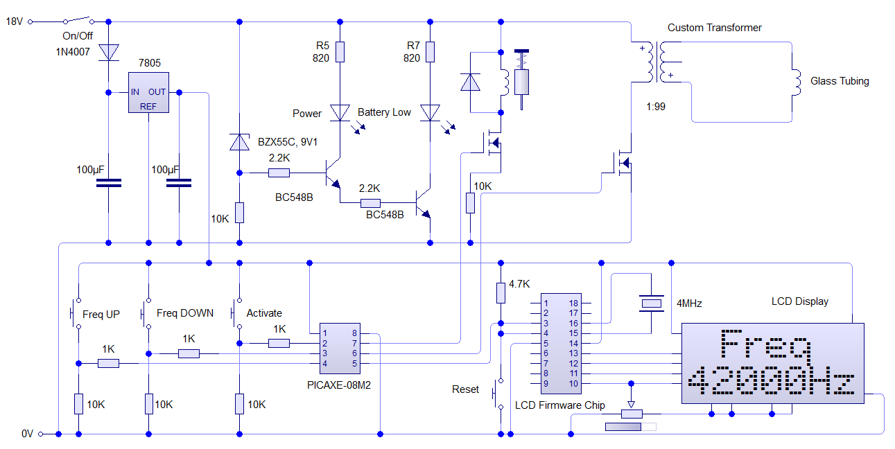
This code worked much better than my previous attempts, however the timing was not accurate enough for my liking. Rather than modifying the code again, which code lead to more problems, and due to my time constraints, I decided to write the program to the PIC16F819. This is an inexpensive 18 pin IC that uses a 4MHz resonator to operate. The timing function was improved greatly. From my LCD board I noticed that the backlit display did not need to be wired up separately as it already had the voltage supply rail going to it through a SMD resistor. Although I though this was pointless it does mean I can cut an extra resistor and wires from my final design, reducing valuable veroboard space. For my final design I held Read/Write and Vss pins to ground, D4-D7 along with Enable and Reset was connected to the microcontroller accordingly. Pin 3 of the LCD was connected to a potentiometer to control contrast. The only big alterations as such were putting pin 18 high on the microcontroller and connecting it to voltage supply pin of the LCD. This was just a precaution if the a voltage surge went though the circuit, it would blow the chip rather than the LCD. Which would mean repairing the circuit would not cost excessive time and money. Also, since the Vout of the PIC pin is always under 5 volts, the backlit of the LCD should last much longer. ( A problem I always have with cheap LCD screens) Below shows my final circuit design of the LCD along with test photos.
 |
| Schematic of LCD Firmware Chip |
 |
| LCD working on breadboard |
 |
| Close up of LCD Display |
Voltage Indicator Circuit:
As a simple extension to the circuit, I have decided to add a simple voltage indication circuit. This will alert the user when the batteries in the handheld device become low. From an online source I found this
schematic. This was more suited for a PP3 9V battery. I altered the circuit to accommodate our 18V supply. The diode was replaced with a 9.1V Zener and adjusted protective resistor values were calculated. Below shows the modified circuit.
 |
| Voltage Regulator Circuit |
From this diagram I built it up on breadboard
 |
| Battery Low indicator when voltage drops below 10 volts |
Solenoid
For the solenoid, a simple interface circuit was constructed using a mosfet and a 10K pull down resistor at the gate. This was connected to the output of the PIC. The solenoid has a diode placed across it to prevent any back EMF. Below shows the design and test of the circuit.
 |
| Solenoid Schematic |
'C:\Users\Michael John\Documents\pic solenoid test.plf
let dirsC = 000111
main:
pause 2000 'Wait command
label_2:
high 1
pause 2000 'Wait command
low 1
pause 2000 'Wait command
goto label_2
 |
| Testing of the solenoid working with the PIC |


